Attention, ALL boards use ‘going low’ !!!! DO NOT USE ‘going high’!!
I’m selling the bare (green) motherboard should you want to build your own Megasquirt. I can supply a BOM. Price for a board is $50 + $15 shipment.
To order, Paypal the correct amount to saunter-01kiddie@icloud.com or contact me if you have any questions. When ordering make sure to mention the type of board: “MS3 CPU Board for NA” or “MS3 CPU Board for NB”. You see, I also have boards for the MS3 Pro module, a mistake is easily made.
For some odd reason, a lot of people set the ecu wrongly to going high. Even DIYAutotune says to use ‘going low’ in their instructions. So AGAIN, RTFM and use GOING LOW!!
Installation manual for all cars
INSTRUCTIONS:
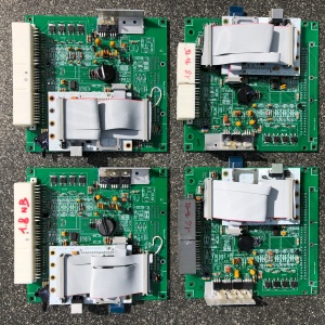
v3 Boards (red color for NB and white color for NA)
MS3 NA Board v3 Assembly instructions and NA v3 BOM
MS3 NB Board v3 Assembly instructions and NB v3 BOM
v2 Boards (green color for both NA and NB)
MS3 NB Board v2 Assembly Instructions and NB v2 BOM
Using the mainboard spark outputs.
This megasquirt uses the MS3X spark outputs. Should you have made the mistake of setting the spark outputs to ‘going high’ instead of ‘going low’, chances are that you burnt your coils. You could also have burnt the spark output transistors or worse, the processor outputs!
Should you have burnt the processor outputs, rest assured, there is a 2nd set of spark outputs that you can use.
Desolder the one leg of resistors R18 (spark A) and R23 (spark B) and lift it from the board (see picture below). Those solder points are no longer being used. Both resistors are now deconnected from the processor. Make sure the legs of the resistors don’t touch the pcb.
We are now going to connect both resistors to 2 different pins on the processor. We will use the pins for the knock module. If you have fitted the knock module, you must remove it unfortunately.
Run a wire from R18 to the top solder hole of the knock module. Run a wire from R23 to the 2nd solder hole of the knock module. Use some heat shrink tube over R23 and R18 to make sure they do not thouch the original solder points.
Since the resistors are only hanging on the board with 1 leg now, use some hot glue to keep the resistor in place. Also use some hot glue to stick the wires to the board.
In TunerStudio, set the spark outputs to ‘main board’ instead of MS3X.

